Abstract
This study investigates the geological, hydrogeological, and engineering geological characteristics of the Son Tra construction stone quarry in An Giang Province, Vietnam. The exploration program included geological mapping, drilling, petrographic analysis, geochemical testing, and geomechanical evaluation over a 10 hectars area. The quarry mainly consists of acidic volcanic rocks of the Nha Trang Formation, including rhyolite and dacitic tuff, which exhibit high strength and favorable physical properties for construction materials. Chemical analyses indicate high silica content and absence of harmful components. Hydrogeological conditions are simple, with limited groundwater occurrence and low water inflow into the mining pit. The estimated construction stone reserve to elevation -20 m is 5,042,400 m³, with a very low stripping ratio of 0.046. The results confirm that the Son Tra quarry is suitable for long-term open-pit exploitation as a high-quality source of construction stone in An Giang Province.
Keywords: Rock, geological features, building materials.
JEL Classifications: 52,53, 54, 56, 57.
An Giang is one of the provinces in the Mekong Delta with significant mineral resources, including various types of stone used as common construction materials to meet the increasing demand for construction in society. At present, the demand for construction stone is continuously increasing, creating favorable conditions for the strong development of the building materials industry in An Giang Province. To ensure stable and long-term stone mining activities, the Provincial People’s Committee has planned designated mining areas, including the stone quarry at Son Tra Mountain, located in Kien Luong Commune. This report presents the geological characteristics of the Son Tra Mountain area to serve the exploitation of stone for common construction materials.
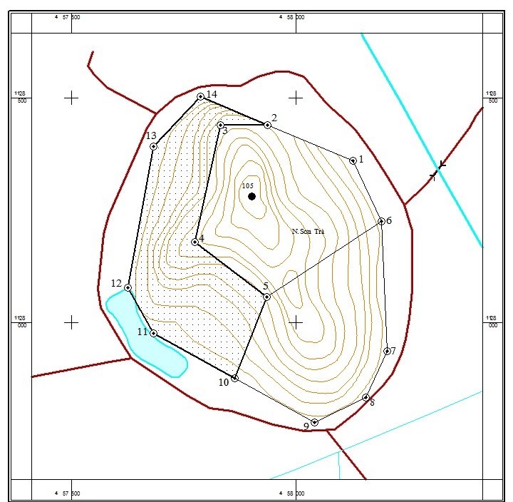
The Son Tra construction stone mining area covers 10 hectares on the western side of the mountain within Kien Luong Commune, An Giang Province. The exploration area is located approximately 7 km south of Kien Luong and about 70 km northwest of Rach Gia.
The boundaries of the area are defined by corner points 2, 3, 4, 5, 10, 11, 12, 13, and 14, with coordinates shown below:
Table 1. Coordinates of Boundary Corner Points
|
Corner points |
X (m) |
Y (m) |
|
2 |
1128.440 |
457.936 |
|
3 |
1128.440 |
457.831 |
|
4 |
1128.179 |
457.774 |
|
5 |
1128.058 |
457.934 |
|
10 |
1127.876 |
457.864 |
|
11 |
1127.976 |
457.682 |
|
12 |
1128.079 |
457.642 |
|
13 |
1128.392 |
457.682 |
|
14 |
1128.503 |
457.787 |
(VN2000 coordinate system, central meridian 105°, 6° projection zone)
Adjacent boundaries:
- North and west: adjacent to mixed garden land and residential houses.
- East: adjacent to the remaining unexplored mountain area.
- South: adjacent to a small lake and barren land.
1. Research Methodology
To evaluate the reserves and quality of construction stone while ensuring construction progress and maximizing exploration efficiency, exploration methods were implemented sequentially with reasonable and economical workloads. The methods and specific workloads are as follows:
Data Collection
The study area had previously undergone several stages of investigation as mentioned in the research history section. Therefore, it was necessary to collect geological documents, particularly drilling survey data, as well as meteorological and hydrological information.
Compilation and Preparation of Geological Maps at a Scale of 1:2,000
The objective of this work was to delineate geological boundaries for reserve calculation and to support future environmental impact assessment reporting. Since the exploration target consists entirely of acidic volcanic rocks almost completely covered by weathered materials, geological traverses along survey lines were of limited effectiveness. Therefore, traverses were conducted along exposed rock boundaries combined with exploration drilling data. Geological surveys also utilized artificial outcrops, excavation pits, and local wells to collect geological information and descriptions. Workload:
- Geological mapping area at a scale of 1:2,000: 10 ha
- Geomechanical samples: 18 samples
- Semi-quantitative spectral analysis samples: 10 samples
- Silicate chemical analysis samples: 10 samples
Drilling Work
As mentioned above, exploration drilling works were carried out to determine layer thickness, collect samples for stone quality analysis, and detect possible alterations with depth due to weathering or tectonic activity.
Drill holes were arranged along lines extending from the mountain foot to the slope with inclinations ranging from 10° to 20°, mainly covered by mixed forest vegetation. Therefore, the selected drilling equipment was the Chinese-made XJ.100 drilling machine. Drilling Workload:
- Number of drill holes: 8
- Total drilling length: 120 m
- Core recovery ratio:
- Bedrock layer: 95%
- Overburden layer: 90%
Table 2. Drilling Coordinates, Elevation, and Workload
|
Drill Hole |
Coordinates |
Elevation H (m) |
Drill Depth (m) |
Overburden Thickness (m) |
Rock Thickness (m) |
Rock Thickness to -20 m Elevation |
|
|
X (m) |
Y (m) |
||||||
|
LK1 |
1.128.500 |
457.788 |
7,5 |
5,0 |
2,1 |
2,9 |
25,4 |
|
LK2 |
1.128.440 |
457.831 |
54,0 |
5,0 |
1,8 |
3,2 |
72,2 |
|
LK3 |
1.128.179 |
457.774 |
67,0 |
5,0 |
1,9 |
3,1 |
85,1 |
|
LK4 |
1.128.058 |
457.934 |
54 |
40,0 |
1,6 |
38,4 |
72,4 |
|
LK5 |
1.127.876 |
457.864 |
6,5 |
20,0 |
2,5 |
17,5 |
24,0 |
|
LK6 |
1.128.080 |
457.625 |
9,5 |
20,0 |
2,6 |
17,4 |
26,9 |
|
LK7 |
1.128.394 |
457.684 |
7,8 |
20,0 |
2,5 |
17,5 |
25,3 |
|
LK8 |
1.128.069 |
457.779 |
27,0 |
5,0 |
2,4 |
2,6 |
44,6 |
|
Average: |
2,2 |
12,8 |
47,0 |
||||
Sampling Work
To support reserve estimation objectives, the following samples were collected, processed, and analyzed during the project implementation:
Petrographic Samples
Samples measuring 3 × 6 × 9 cm were collected from fresh rock, evenly distributed across the exploration area and depth. Samples were analyzed at the Southern Geological Mapping Federation Analysis and Testing Center.
- Total collected samples: 18
- Petrographic analysis samples: 10
- Microscopic structural imaging samples: 5
Semi-Quantitative Spectral Analysis Samples
Bulk samples were collected from exploration works, evenly distributed throughout the exploration area and depths, to evaluate trace element contents and detect the presence of rare elements.
- Total analyzed samples: 10
Silicate Chemical Analysis Samples
Samples were collected as lump or point samples evenly distributed across the exploration area and among rock types, usually at the same locations as geomechanical samples. Purpose: Determine chemical composition, Assess harmful components such as SO₃. Total analyzed samples: 10. Analyzed parameters: SiO2, TiO2, Al2O3,Fe2O3, FeO, MnO, MgO, CaO, Na2O, K2O, P2O5, LOI, SO3 and H2O.
Geomechanical Samples
Samples were collected from exploration works and distributed evenly across the area and drilling depths. Total samples: 18. Analyzed parameters: specific gravity, bulk density, water absorption, natural compressive strength, saturated compressive strength, void ratio, porosity, softening coefficient, internal friction angle, cohesion.
2. Research Results
The exploration target consists of acidic volcanic rocks belonging to the Nha Trang Formation. Within the exploration area, the rock is completely covered by a weathered surface zone of bedrock. The overburden thickness ranges from 1.6–2.6 m, averaging 2.2 m.
Data from outcrops and drilling indicate a very distinct boundary between fresh rock and weathered material, with no partially weathered zones or only very thin partially weathered layers included in the overburden. This characteristic is favorable for reserve calculation.
2.1. Petrographic and Mineralogical Characteristics
The acidic volcanic rocks of the Nha Trang Formation include: Porphyritic rhyolite, Dacitic tuff, Rhyodacitic tuff, Rhyolitic tuff. The rocks are massive, clastic in texture, with altered microgranular groundmass, and colors ranging from greenish gray and bluish gray to dark gray.
The rock is fine-grained, light gray with pinkish hues or greenish gray, with phenocrysts embedded in a fine-grained matrix. The rock is massive, hard, and angular.
Table 3. Petrographic Characteristics
|
Mineral |
Content (%) |
||
|
Highest (%) |
Lowest (%) |
Average (%) |
|
|
Clasts – Phenocrysts |
12 - 14 |
1 - 2 |
6 - 8 |
|
Potassium Feldspar |
5 - 6 |
1 - 2 |
3 - 4 |
|
Quartz |
3 - 4 |
1 - 2 |
2 - 3 |
|
Plagioclase |
5 - 6 |
1 - 2 |
3 - 4 |
|
Acidic volcanic fragments |
7 - 8 |
- |
2 - 3 |
|
Matrix |
99 - 98 |
88 - 86 |
95 - 96 |
|
Feldspar, quartz, silica, sericite, chlorite |
96 - 94 |
87 - 84 |
90 - 92 |
|
Ore minerals, iron oxides |
2 - 3 |
1 |
1 - 2 |
2.2. Chemical Composition
Table 4. Chemical Composition
|
Oxide |
Content (%) |
||
|
Lowest (%) |
Lowest (%) |
Lowest (%) |
|
|
SiO2 |
72,62 |
65,90 |
70,22 |
|
TiO2 |
0,45 |
0,30 |
0,37 |
|
Al2O3 |
14,94 |
11,77 |
12,96 |
|
Fe2O3 |
4,16 |
3,29 |
3,58 |
|
MKN |
3,59 |
1,89 |
2,69 |
|
Σ |
92,75 |
88,64 |
89,82 |
The silicate chemical analysis results indicate that the rocks belong to the acidic volcanic group. Comparison with average volcanic rock compositions reported by Deli (Huỳnh Trung, 1988) shows strong similarity with acidic volcanic rocks. No harmful components such as SO₃ were detected in the analyzed samples.
2.3. Geomechanical Properties of the Rock
The geomechanical properties of the rock were determined based on the following parameters:
Table 5. Geomechanical Properties
|
Geomechanical Parameters |
Result |
||
|
Highest |
Lowest |
Average |
|
|
Bulk density (g/cm³) |
2,72 |
2,67 |
2,69 |
|
Specific gravity (g/cm³) |
2,74 |
2,7 |
2,72 |
|
Saturated water absorption (%) |
0,48 |
0,06 |
0,23 |
|
Porosity (%) |
1,84 |
0,37 |
1,11 |
|
Softening coefficient |
0,94 |
0,87 |
0,90 |
|
Dry compressive strength (kg/cm²) |
1238 |
895 |
1042,5 |
|
Saturated compressive strength (kg/cm²) |
1264 |
784 |
940,21 |
|
Natural cohesion (kg/cm²) |
328 |
242 |
275,43 |
|
Natural internal friction angle (degrees) |
37o50’ |
32 |
34o |
Compared with the geomechanical standards for igneous rocks used as construction materials, the rock in the mining area fully meets and exceeds both the Company’s requirements and Vietnamese standards for construction stone.
Construction stone is processed by drilling and blasting the mountain rock into fragments of various sizes, then manually or mechanically crushed into products suitable for construction and transportation works according to the following specifications:
- 1×2 stone aggregate
- 20×30 stone aggregate
2.4. Hydrogeological Characteristics
2.4.1. Surface Water
Surface water within the mining area is not found inside the exploration boundary but occurs only in rice fields during the rainy season and in the internal canal system connected to the Năm Thước Canal north of the mine area. According to information collected from local residents, water is available only during the rainy season; from the end of the rainy season until late November, surface water is almost completely depleted, and domestic water must be transported from other areas.
The chemical composition of surface water collected from the internal canal system is represented by the following Kurlov formula:
|
M0.08 |
HCO357 SO421 Cl20 |
pH7.19 |
|
(Na + K)39 Ca38 Mg18 |
Water characteristics: pH: 7.19
Total mineralization: 0.083 mg/L
NO₃⁻ content: 0.49 mg/L
NO₂⁻ content: 0.02 mg/L
Total Fe: 0.64 mg/L
Hydrochemical type: Sulfate - Bicarbonate - Sodium Potassium
These parameters indicate poor water quality, unsuitable for domestic consumption and drinking purposes, and usable only for irrigation and environmental treatment systems.
2.4.2. Groundwater
Based on the geological structure of the mine, petrographic characteristics, groundwater-bearing capacity of rock layers, hydrogeological survey traverses, and exploration drilling data, the hydrogeological units are divided as follows:
- Groundwater-bearing Layer in the Hậu Giang Formation: Groundwater samples collected from wells used by local residents surrounding the study area were identified as belonging to the Hậu Giang Formation aquifer, with analytical results as follows:
Table 6. Groundwater Analysis Results
|
Parameter |
Sample N4 |
Sample N5 |
Average |
|
pH |
6.4 |
6.5 |
6.45 |
|
Total mineralization |
0.22 |
0.18 |
0.20 |
|
Hardness |
121 |
129 |
125 |
|
Cl⁻ |
0.30 |
0.29 |
0.295 |
|
Total iron |
0.41 |
0.52 |
0.465 |
|
N-NO₃ |
1.17 |
1.29 |
1.23 |
|
N-NH₃ |
0.005 |
0.01 |
0.0075 |
- Water-bearing Layer within the Weathered Zone of the Nha Trang Formation: The thickness of this layer ranges from 1.6 m (LK4) to 2.6 m (LK6), averaging 2.2 m. The groundwater-bearing capacity varies due to changes in lithology, degree of weathering, and weathered zone thickness in each area.
The layer consists mainly of: Clayey silt with poor water-bearing capacity or Gravel mixed with sandy clay capable of containing water but unevenly distributed.
Within the exploration area, this layer occurs on slopes where water rapidly drains toward the surrounding lowland plains. Therefore, actual drilling surveys encountered no groundwater. During drilling through gravelly layers, drilling fluid losses were significant.
Recharge to this layer mainly comes from rainfall, while discharge occurs primarily toward surrounding low-lying plains and partially infiltrates fractured zones within the bedrock.
- Fracture Water-bearing Zone in Acidic Volcanic Rocks: Immediately beneath the completely weathered layer averaging 2.2 m thick lies fresh bedrock. Secondary alteration mainly includes chloritization and sericitization, while fractures are mostly sealed microfractures. Based on lithological composition, petrographic characteristics, and layer thickness as described above, this hydrogeological unit is considered water-poor. Actual exploration drilling confirmed that no groundwater was encountered.
2.4.3. Forecast of Water Inflow into the Mine
The stone quarry will be exploited by open-pit mining, with the pit area coinciding with the exploration area (10 ha). The maximum mining depth reaches elevation -20 m.
According to hydrogeological investigation results, the only water flowing into the mining pit is direct rainfall entering the pit (Qrain).
Rainwater inflow is calculated using the formula:
Qrain = S × Z
Where:
S = mining pit area (m²)
Z = maximum daily rainfall = 0.103 m (recorded at Kien Luong Station on August 20, 2009)
Catchment area (mining pit area): S = 100,000 m²
Substituting values into the equation:
Qrain = 100,000 × 0.103 = 10,300 m3/day
Thus, during peak rainfall events, the volume of water entering the mining pit is relatively large. To prevent flooding within the pit, drainage ditches may be excavated along the upper edge of the pit to divert runoff and rainwater away through pre-constructed drainage channels.
Therefore, surface water and groundwater have little impact on mining operations. Water entering the mining pit mainly consists of direct rainfall and surface runoff within the catchment area.
2.5. Engineering Geological Characteristics
Based on field exploration results and laboratory analyses of soil and rock samples, the engineering geological profile of the exploration area can be divided into two principal layers from top to bottom according to their physical and mechanical properties.
2.5.1. Soft Unconsolidated Soil Layer
Based on lithology, geomechanical properties, and groundwater-bearing characteristics, this layer can be subdivided into two sublayers.
- Layer 1a - Clay and Silty Clay: This layer ranges from semi-hard to hard consistency and contains minor gravel in the upper part. It represents the completely weathered zone of acidic volcanic rocks and is distributed across the entire exploration area. Composition: clay and silty clay with minor gravel, yellowish-brown color, semi-hard to hard consistency. Thickness ranges from 1.6 m (LK4) to 2.6 m (LK6); average: 2.2 m.
Layer 1b - Loose Hard Soil from Incompletely Weathered Material: This layer is a weathering product of acidic volcanic rocks and occurs throughout most of the mine area directly overlying bedrock. Thickness varies from: 0 m (in most drill holes) to 2.6 m; average: 1.3 m. The material mainly consists of coarse- to fine-grained sand with dense structure. Under external force, it disintegrates into coarse- to fine-grained sand composed of angular rock fragments.
2.5.2. Hard Rock Layer
This layer is almost entirely covered by the unconsolidated soft layer above. Across the mining area, it is encountered at varying depths, from 1.6 m at drill hole LK4 to 2.6 m at drill hole LK6.
Exploration works have not fully determined the thickness of the hard rock layer. According to regional geological data, the maximum thickness exceeds 100 m. In the Tra Duoc quarry area, the maximum confirmed thickness reaches only 50 m.
Core samples from exploration drilling generally exhibit poor integrity, with many cores cut by calcite veins and sealed microfractures.
Field investigations and laboratory testing indicate that hydrogeological and engineering geological conditions are generally favorable for mining operations. However, during exploitation, attention should be paid to the following engineering geological hazards:
- Slope failure along pit walls during mining operations. To prevent this phenomenon, pit wall slopes must remain below the allowable safe angle, especially during the rainy season when soils and rocks become saturated.
- Flooding during mining operations. As analyzed above, the only water source entering the pit is direct rainfall; therefore, appropriate dewatering measures must be applied.
2.6. Slope Angle of the Open Pit
The Son Tra construction stone quarry in Kien Luong Commune, An Giang Province will be exploited by open-pit mining. The planned pit walls will cut through the weathered zone of acidic volcanic rocks and into the bedrock extraction layer.
The quarry belongs to the category of mines with simple hydrogeological and engineering geological conditions.
- The upper layer consists of silty clay mixed with gravel, having poor water-bearing capacity.
- The lower layer consists of hard acidic volcanic rock with great thickness and moderate permeability.
- The stable slope angle for the overburden above the acidic volcanic rocks is: 30°28′.
- For the hard rock group, the stable slope angle is: 56°25′.
The hydrogeological and engineering geological investigation results generally satisfy the requirements for mine drainage design and stable pit slope design.
2.7. Mineral Reserves
2.7.1. Reserve Estimation Results
Table 7. Total Reserves Calculated to Elevation -20 m
|
No. |
Reserve Block |
Block Area (m²) |
Overburden Thickness (m) |
Rock Thickness (m) |
Rock Reserve (m³) |
|
1 |
K1-121 |
9,046 |
2.1 |
40.5 |
366,665 |
|
2 |
K2-121 |
38,590 |
2.2 |
52.1 |
2,008,610 |
|
3 |
K3-121 |
52,710 |
2.2 |
50.6 |
2,667,126 |
|
Average |
|
2.2 |
47.73 |
|
|
|
Total |
100,346 |
|
|
5,042,400 |
|
The calculated Category 121 reserve to elevation -20 m is 5,042,400 m³.
Thus, based on the exploration grid, three Category 121 reserve blocks were delineated.
The calculated Category 121 reserve to elevation -20 m is 5,042,400 m³.
2.7.2. Stripping Ratio
According to the reserve calculation guidelines for non-metallic minerals issued by the General Department of Geology, the stripping ratio is determined as the total overburden volume divided by the total rock reserve.
Table 8. Stripping Ratio Calculation
|
No. |
Reserve Block |
Block Area (m²) |
Overburden Thickness (m) |
Rock Reserve (m³) |
Overburden Volume (m³) |
Stripping Ratio |
|
1 |
K1-121 |
9,046 |
2.1 |
366,665 |
19,298 |
0.053 |
|
2 |
K2-121 |
38,590 |
2.2 |
2,008,610 |
84,898 |
0.042 |
|
3 |
K3-121 |
52,710 |
2.2 |
2,667,126 |
115,962 |
0.043 |
|
Average |
|
2.2 |
|
|
0.046 |
|
|
Total |
100,346 |
|
5,042,400 |
220,158 |
|
|
The stripping ratio may also be calculated using the total overburden volume divided by the total mine reserve:
|
Stripping Ratio = |
220,158 |
= 0.046 |
|
5,042,400 |
Therefore, the stripping ratio for the entire mine is 0.046.
This means that for every 1 m³ of rock extracted, only 0.046 m³ of overburden must be removed. This is considered a very low stripping ratio.
3. Conclusion
The exploration work for the Sơn Tra construction stone quarry in Kien Lương Commune, An Giang Province accomplished the following principal tasks:
- Topographic surveying of the Sơn Tra construction stone quarry area at a scale of 1:2,000 over an area of 0.1 km².
- Preparation of a geological map of the quarry at a scale of 1:2,000 covering an area of 0.1 km².
- Estimation of construction stone reserves within the exploration area, with Category 121 reserves totaling 5,042,400 m³, accounting for 100% of the estimated reserve.
- The rock quality meets and exceeds the standards for igneous rocks used as construction materials. No mineralization indications were observed, and the content of useful minerals is very low and of no industrial value.
The exploration work closely followed the technical methods and workload specified in the exploration project. The exploration results accurately reflect the reserve quantity and quality of construction stone resources within the mining area.
Truong Dang Quang1
1Faculty of Engineering - Technology - Environment, An Giang University,
Vietnam National University Ho Chi Minh City
REFERENCES
1. An Giang Construction Assembly Company, 2002. Exploration Report for the Ba Doi Mountain Construction Stone Quarry, An Hao Commune, Tinh Bien Commune, An Giang Province.
2. Dang Tran Bang et al., 1987. Calculation of Solid Mineral Reserves.
3. Doan Sinh Huy, 1998. Geological Exploration Report for the Nui Gio Construction Stone Quarry, Binh Long – Binh Phuoc. Geological Archive – Hanoi.
4. Nguyen Ngọc Hoa et al., 1991. Geological Mapping and Mineral Exploration Report at a Scale of 1:200,000 for the Southern Delta Sheet Group. Geological Archive – Hanoi.
5. AN GIANG Investment and Construction Company, 2006. Exploration Report of the Tra Duoc Lon Construction Stone Quarry, Binh An Commune, Kien Luong Commune, AN GIANG Province.